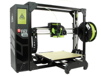
Lulzbot Taz 5 to Taz 6 Toolhead Upgrade Tutorial

How to upgrade your Lulzbot Taz 5 3D printer toolhead (v2) to the Taz 6 toolhead (v2.1)
At Print Your Mind, we are dedicated to providing the best possible support and assistance to our customers. Keeping in that theme, this tutorial is intended to help owners of the Lulzbot Taz 5 3D printer perform an upgrade to the toolhead. This will result in converting the stock toolhead to that of the recently released Lulzbot Taz 6 for better cooling.
Benefits of this upgrade:
- more effective and quieter cooling for the hexagon hotend
- additional cooling for the part being printed by symmetrically cooling from both sides
Requirements for the upgrade:
- fan shrouds (left, right, extruder)
- extruder mount
- extruder guide
- upgraded idler as per the Lulzbot tech bulletin (see our Changing Your Idler tutorial
Note: We recommend to use ABS or other heat-resistant material due to the proximity of the fan shrouds to the nozzle.

Purchased parts:
- 1 x 5V 40mm cooling wire (2 wire)
https://www.lulzbot.com/store/parts/40mm-pelonis-low-flow-fan - 2 x 24V 40mmx40mmx10mm cooling fan (2 wire)
https://www.lulzbot.com/store/parts/40mm-pelonis-low-flow-fan - 9 x 3mm brass heat inserts (M3 x 3.8mm length)
https://www.lulzbot.com/store/parts/heat-set-insert-tapered-m3-05mm-internal-thread-38mm-l-x20

Tools and hardware:
- allen wrenches or hex keys (H2.0, H2.5, H3.0)
- wire strippers
- soldering iron
- wire shrink wrap
- dupont wire crimper (optional)
- dupont male connectors (optional)
- JST connectors (optional)
Detailed steps:

2. Raise the Z axis to about 60mm, or any height that gives you sufficient clearance to work underneath the extruder.
3. After retracting the filament from the extruder, disconnect the power to the printer, as well as the main wire harness for the extruder. This is also a good time to remove the filament guide tube so that it's out of the way.

4. Remove the stock fan shroud by unscrewing the 2 M3 screws using an H2.5 hex bit.

5. Remove the 5mm "squirrel cage" fan by removing the single M2 screw using an H1.5 hex bit.

6. Untwist the wires of both fans.
7. Unscrew the extruder housing from the X carriage by removing the 2 M4 screws from below using an H3.0 hex bit.
You should now have a "deconstructed" toolhead.
Note: We also chose to print a new set of herringbone gears in "Lulzbot Yellow" to accent our new toolhead. :)
8.Remove the 5 M3 screws holding the extruder mount and extruder guide to the X carriage.
9. Next we need to add the brass inserts to the new extruder mount in order to hold the fan shrouds reliably.
Simply place the smooth part of the insert into the hole and gently press it flush into place using a preheated soldering iron. Be careful to only touch the brass and do not press too hard. It only take a couple of seconds to heat the brass and it will sink into the plastic.
You will use 2 on each side of the extruder mount for the side fan shrouds, and one in the middle for the extruder fan shroud. The additional 4 will be used in the lower holes of the side fan shrouds.


10. Mount the extruder guide on the X carriage using 4 M3 screws and an H2.5 hex bit.
11. Slide the bottom edge of the extruder mount into the extruder guide and secure with a single M3 screw at the top using an H2.5 hex bit.
12. We have 2 options for changing the wiring for the fans. The simplest way is to simply snip off the existing fans and splice our new ones on to the existing wires. But if you have access to Dupont connectors and a Dupont wire crimper, you can perform a cleaner installation. If you opt for the second method, skip ahead to step 24 below.
13. To perform the splice, you will need wire strippers, a soldering iron, and suitable sized heat shrink wrap. Start by exposing 20-25mm of bare wire on each end of the new fan wires, as well the ends of the wire from the harness.
14. Twist the ends of each bare wire so that the multiple strands lie together to neatly form a uniform cylinder.
15. Place the red (positive) wire from each of the new fans so they are parrel to each other, and twist them together to for a single wire. Repeat for the black (negative) wires.
16. Place the heat shrink wrap over each end of the wire coming from the harness, and ensure that they are well enough away from the bare wires where the splicing will occur, so as not to cause them to melt prematurely.
17. Starting with the red wires, make an 'X' in the middle with the joined pair from the fans and the single red wire from the harness. Gently twist them together so they remain inline with each other and lay flat as to not cause any lumps. This will make the next step easier when soldering the wires. Repeat with the black wires.
18. Heat up the soldering iron and apply a sparing amount of solder to the bundle of red wires to evenly coat the wires and ensure the joint does not come apart. Avoid applying too much solder that results in a lump or ball. This will interfere with the heat shrink wrap. Remember, less is more and you should be able to still see the wires when finished soldering. Repeat with the black wires.
19. After allowing each joint to cool, slide the heat shrink wrap over each set of wires and ensure complete coverage. Gently heat the heat shrink with a lighter or other suitable heat source to complete the splice.
20. To demonstrate the 2nd option, start by removing the positive and negative wires for the 2 existing fans. For the negative wires, you will need to poke through the sticker to release the connectors.


21. With both fans removed from the harness, we can prepare new wires with female SJT connectors by crimping male Dupont pins onto 2 pairs of connectors. We made the pairs slightly different lengths, just so we can distinguish them later when connecting the new fan wires.
22. Insert the Dupont pins into the wiring harness, keeping the negative (black) wires on the side of the harness with the sticker. The connector for the side cooling fans will be closest to the wires for the stepper motor.
23. Add the corresponding male SJT connector to the new 5V 40mm cooling fan for the extruder, as well as a male SJT connector to the 24V 40mm cooling fans that are also spliced together.
24. We can now mount the extruder with the 2 M4 screws using an H3.0 hex bit.
25. Mount each of the side fans to the extruder mount with a single M3 screw for each in the upper rear corner only. Be sure to use a button-head screw so as not to interfere with the fan itself.


27. Check the clearance between the heater core and the fan shroud(s) and adjust to give adequate clearance.


28. Mount the extruder cooling fan with an M3x25mm screw so that it attaches to the brass insert in the extruder mount.

29. Enjoy your newly upgraded extruder!

This guide is licensed CC BY-SA 4.0 International. LulzBot® is a
registered trademark of Aleph Objects, Inc.


